Introduction In this experiment you will investigate the frictional forces inherent in laminar and turbulent pipe flow. Pipe Flow involves an experimental apparatus with.
Experiment No 1 Flow Through A Sluice Gate
The purpose of this experiment is to find pressure loss head loss for several pipe components over a range of flow rates and compare the experimental findings to theoretical calculations.

. Hydraulics Team E5 February 12 2015 printed 5222016 teame5hydraulics-160522015341 p. Liquids only flow through pipes if forced to do so by pressure caused by a pump of by gravity. Therefore we measured the friction factor of the pipes using our measurements.
1 Pressure drop at sudden enlargement The test section consists of a 10mm diameter bore with a sudden enlargement to 20mm diameter. 4 measuring the diameters of pipes and a graduated cylinder and stop watch for recording flow rates were used the main component of this lab was the pipe apparatus that we ran the experiment on. The experiment was undertaken to measure the head lost in the pipe due to shear stress between the fluid and the wall of the pipe.
The experiments were performed in incompressible turbulent pipe flow over a wide range of Reynolds numbers and the results indicate that the correction term. Different flow rates were introduced along with a different diameters and roughness of the pipes. Formulation Head loss hL is directly proportional to the Pipe frictional constant f Length of the pipe L in m.
Fluid Flow Minor Losses Purpose. Fluid Mechanics Lab Report. A mercury manometer soon to be replaced with a digital flow meter a collection tank for the 18 inch pipe.
The experiment also developed turbulent flow laminar flow and compared measured and calculated. 28 Full PDFs related to this paper. I Dark blue circuit experiment a Obtain the relationship between the straight pipe head loss and the volume flow rate h L.
Objective is to arrive at pipe roughness numbers and compare them with literature. This experiment was carried out to investigate the friction factor as well as the major and minor head losses because of friction in three different types of bore pipes namely elbow pipes expansion and construction pipes and long pipes. The flow rate may be confirmed by using the volumetric measuring tank of the hydraulics bench.
18 12 1 and 2 inches. Lecture handout-Fluid PropertiesJuly 2017 Other related documents. Ndiritu thembalethu mhlanga 886185 university of the.
By measuring the pressure drop and flow rate through a pipe an estimate of the coefficient of friction friction factor will be obtained. The flow channel has been designed to allow students a wide range of experiments on water flow in an open channel under different flow conditions and analyze the effects of test models of various shapes on water flow. Pipe Flow U1425230 f Summary This lab was directed at observing the effects of friction on fluid flow in different pipes.
3 pipes with carried diameter were used to determine the the Reynolds Number Re as well as the friction coefficient for each of the three pipes. Objective of the Lab We need to experimentally study the pipe flow in both laminar and turbulent flow regime. Consider a sudden enlargement in pipe flow area from area A 1 to area A 2.
Venturi Flume Experiment Report REV 1. Study the Pipe Flow in both Laminar and. Four pipes of different diameters.
A short summary of this paper. Two manometer are provided. Report Data Analysis In addition to tables showing all experimental results the report must include the followings.
Ramith Bulumulle 24698512 Don Gayanga Millevithanatchy 24829781 Zhi Ying Lim 23725540 26102014 fAbstract The principle examined in this experiment was how the frictional flow of a fluid in a pipe. ES2A7 laboratory Exercises Section I Theoretical Preparation 1. The data obtained from the experiment was contrasted against the.
125 hp pump pumps water through the smallest 18 inch pipe. Pipe flow laboratory report civn3013 basic hydraulics pipe flow experiment lab report for prof. Exam 12 June 2014 questions and answers.
MEC2404 Frictional Flow in Pipe Lab Report Done by. The flow channel is one of the most important tools available for the teaching of hydraulic principles.
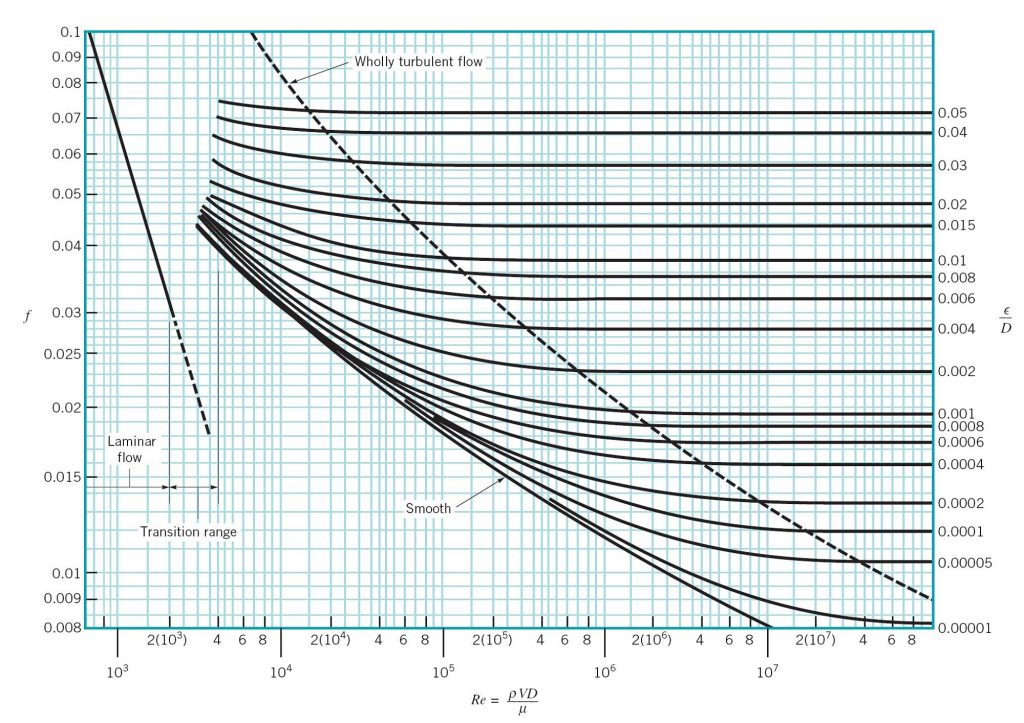
Experiment 4 Energy Loss In Pipes Applied Fluid Mechanics Lab Manual

Osbourne Reynolds Apparatus Experiment University Engineering Marked By Teachers Com

Patrick Hanley Phd On Twitter Structural Analysis Aerodynamics Aircraft Design
Experiment 11 Reynolds Number And Transitional Flow

Gizmos Convection Cells Answer Key Convection Cell Answer Keys

Nusselt Generative Design The Library Of Babel Flow Arts

Learn About The Periodic Table Homegrown Learners Chemistry Science Classroom Decorations Science Chemistry

Understanding Purpose Of Salt Bridge Electrochemistry Physical Chemistry Teaching Chemistry
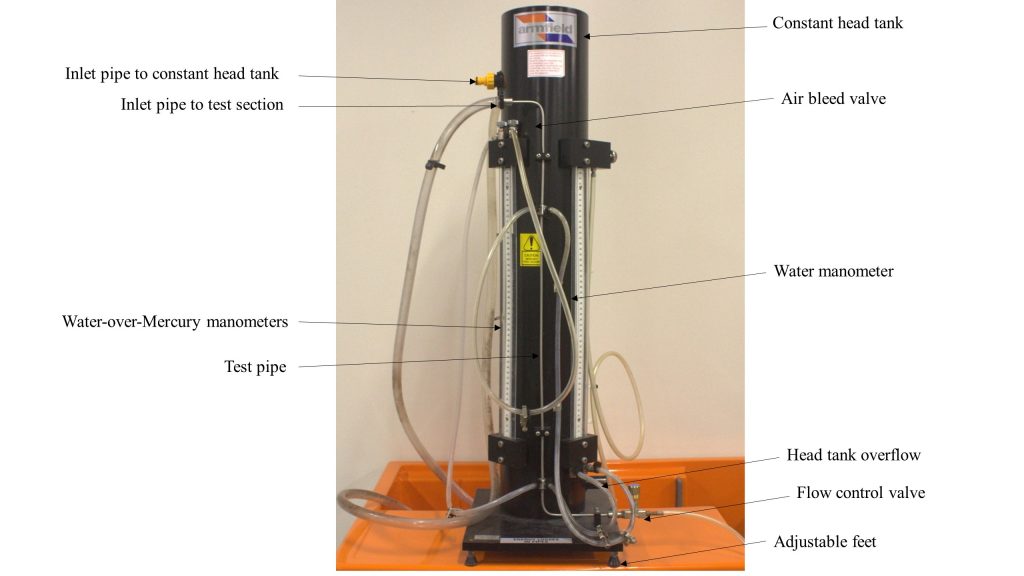
Experiment 4 Energy Loss In Pipes Applied Fluid Mechanics Lab Manual

What Is A Sankey Diagram Definition History Examples Sankey Diagram Diagram Flow Chart
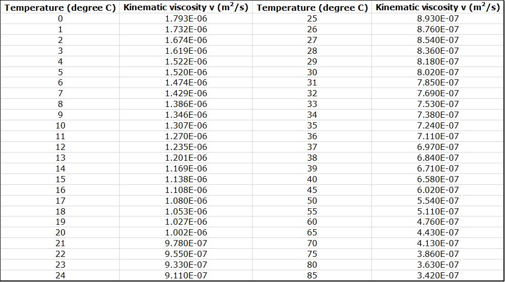
Experiment 4 Energy Loss In Pipes Applied Fluid Mechanics Lab Manual

Walking On Water Fun Non Newtonian Fluid Experiment Newtoniano Liquidos
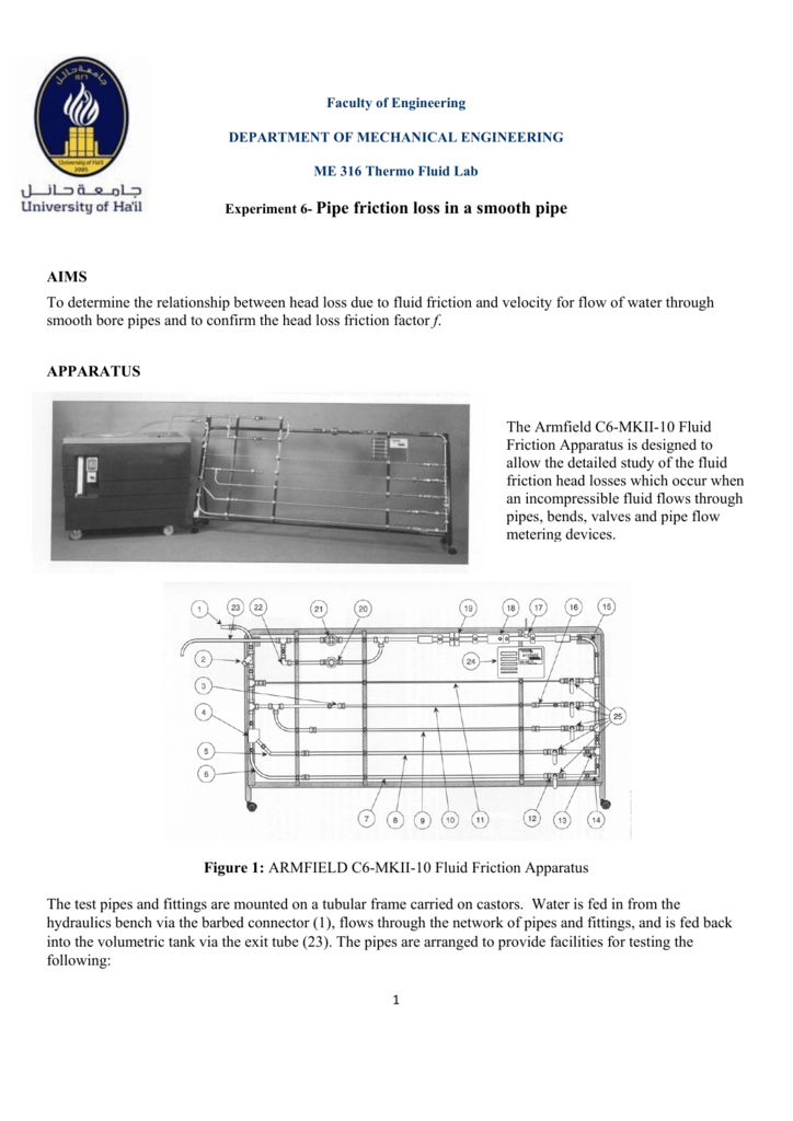
Experiment 6 Pipe Friction Loss In A Smooth Pipe
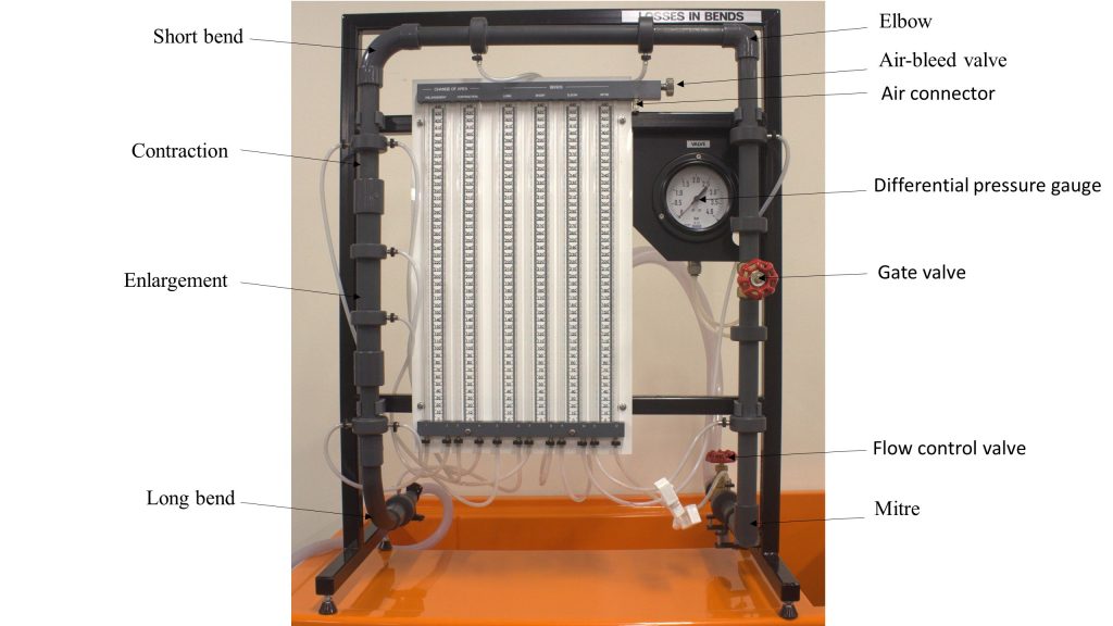
Experiment 3 Energy Loss In Pipe Fittings Applied Fluid Mechanics Lab Manual

Experiment 4 Energy Loss In Pipes Applied Fluid Mechanics Lab Manual

How To Write A Chemistry Lab Report Check More At Https Nationalgriefawarenessday Com 24692 How To Lab Report Template High School Chemistry Labs Lab Report
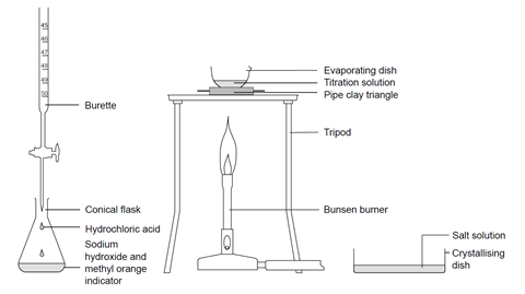
Titrating Sodium Hydroxide With Hydrochloric Acid Experiment Rsc Education

Pdf Laboratory Experiment Flow Through Pipes
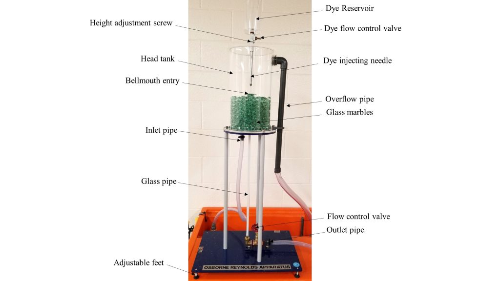
Experiment 7 Osborne Reynolds Demonstration Applied Fluid Mechanics Lab Manual
